Overview - About 'A.W.E.S.O.M.-O 9000'

'A.W.E.S.O.M.-O 9000' (formerly known as '9000' Aalborg') is an intelligent autonomous line-tracking car-like robot and is shown in the picture to the right. The robot is build on the basis of the mechanical platform of a standard RC-car.
A.W.E.S.O.M.-O 9000 is designed and build with a single purpose in mind. It has to be able to complete the track in the RoboCup competition at DTU.
The robot has been developed by group E504 at Aalborg University in the autumn of 2006 as a 5th semester project. The theme of the semester was real time feedback systems so the primary focus in the development of the robot has been its feedback systems. This comprises the DC/DC converter, the speed regulation and the line-tracking regulation.
News
Sunday, 29 January 2012
This site has not been updated for a long time. Today, however, I have uploaded a few new videos from RoboCup 2008 to RoboCup 2010, and I have added a new section where you can find the results from RoboCup. I am planning to update this page more frequently.
Monday, 16 April 2007
We are sorry that we have not updated the homepage of A.W.E.S.O.M.-O 9000 recently, but the RoboCup competition ended rather poorly for A.W.E.S.O.M.-O 9000. In the qualification round, everything went as it should. We finished 8th with 9 points without taking any risks. After the qualification round, everything went wrong. It began with a software bug which was triggered when we made the robot drive in reverse. We wasted many hours before we finally at 5 a.m. Thursday morning found the bug - and it was, of course, quite simple and obvious. After that the robot fell down from the ramp and stairs several times and damaged some connectors and the line sensor. We managed, howewer, to make the robot capable of getting three more points, but because of the hardware damages the robot was unreliable. In the final of the RoboCup competition, the robot was indeed unreliable. For the first run, we used the same code as in the second run of the qualification, but this time the robot crashed at the speed track. In the second, run the robot apparently failed to count all floor transitions. Thus, it made a three point turn a transition too late which happened to be inside a gate. We finished 7th with 8 points.
Tuesday, 10 April 2007
The first day at RoboCup is nearly over. The robot has been tuned to the line and background and is driving very well. The first hurdle, which we have made the robot to overcome, is the speed track. So far we are the fastest!!! The next project is to detect where the different hurdles start so we can adjust the robots behaviour according to the specific hurdle.
Sunday, 8 April 2007
Only two days left before RoboCup begins - we are very excited and looking forward to the competition. We have taken some pictures of the new hardware (distance sensors, bumper and magnet) that we have added to the robot. The pictures can be found in the technical specifications section. Furthermore, we have created a picture page where additional pictures have been placed. We will update it during the competition. The link to the picture page can be found in the download section.
Friday, 31 March 2007
Finally! In the past month the new hardware (distance sensors, bumper and magnet) has been developed. Today we mounted it on the robot and everything is working. That means that we should be able to handle more hurdles like the tunnel and the part of the track with the cones.
Friday, 9 March 2007
We had a status meeting today in which we updated each other on the various improvements on the robot that were launched a month ago. The distance measuring improvement is in progress. It has been decided to use four distance measuring sensors (two on each side of the robot) and the hardware to control them is almost complete. It consists of two small switches and a light metallic plate. Suitable switches has been found, but they still need to be mounted on the robot. It has been difficult to find at suitable permanent magnet that is easy to mount on the robot. A possible solution to the magnet problem was found and will be investigated further. The idea is to use a retractor like those used for lift cards in ski lifts.
Friday, 16 February 2007
We had a meeting today in which we decided several things regarding the future of the robot. The robot is at the moment only capable of following a line and detect and choose its way in branches. Therefore we will make some hardware improvements. This comprises distance measuring, a bumper and a permanent magnet. These simple improvements will make the robot capable of handling more hurdles.
Wednesday, 31 January 2007
Today we all passed our project exam with a great result which we are very happy about.
Monday, 29 January 2007
This web page is created and published. We hope that you will like it.
Results
- Robocup 2007:
- Number 7 with 8 points
- Robocup 2008:
- Number 3 with 15 points
- Robocup 2009:
- Number 14 with 4 points
- Robocup 2010:
- Number 2 with 17 points
- One two-channel 16-bit timer and two three-channel 8 bit timers
- 10-bit A/D converter width eight channels
- 14-bit PWM
- I2C-bus
- Two RS-232 channels
- 53 I/O pins
- Operating frequency form 2 MHz to 20 MHz
- 56 KB flash memory and 3 KB ROM
- One complete round at the test track: video 1 (9.0 MB).
- One complete round at the test track with the camera mounted on the front of the robot: video 2 (8.8 MB).
- The robot from up tilt while driving at the long side and in the curve: video 3 (5.3 MB).
- First run in the qualification round: video 5 (5.5 MB).
- Second run in the qualification round: video 6 (4.6 MB).
- First run in the final: video 7 (18.2 MB).
- Second run in the final: video 8 (18.5 MB).
- Highlights: video 9 (10.4 MB).
- The project proposal (in danish): Autonom linjerobot(41 kB).
- Our 5th semester report (in danish): Autonom linjerobot - styret ved hjælp af klassisk regulering(2,9 MB).
- The official homepage of the RoboCup competition.
- The homepage of Renesas. The manufacturer of the H8/3687 microcontroller.
- The official homepage of Aalborg University (AAU).
- The official homepage of the Studyboard for Electronics and Information Technology (ESN) of AAU.
Technical specifications
Here is a simple description of the individual element of the electronics of the robot. The detailed description is found in the report which can be found in the download item.
Hardware block diagram

The hardware of the robot is divided into two parts: A control part and a communication part. The control part contains the speed regulation and the line-tracking regulation, and the communication part contains the display, the battery sensor and the communication with a PC across a bluetooth/RS232 link.
Line sensor
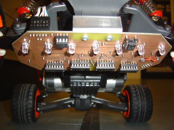
The line sensor is composed of seven infrared emitting diodes and seven photodiodes in pairs which are equally spaced with a distance of approximately 20 mm. The LEDs are modulated with a frequency of 100 kHz and the photodiode currents are filtered in order to attenuate the influence from ambient infrared emitting light sources.
Servo motor

The servo motor is a general-purpose S3003 servo from ROBBE. It is pulse controlled at a frequency of 50 Hz. By warying the length of the pulses the servo position can be changed accordingly. The servo has a transit speed of 4.37 rad/s and a torque of 32 Ncm when operated at ~5 V.
Speed sensor
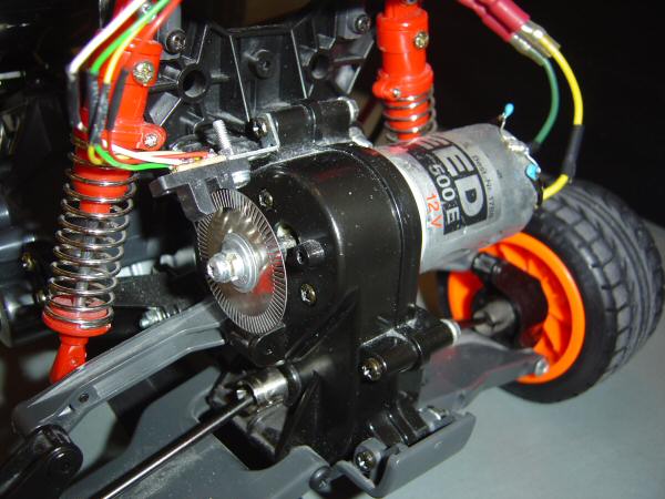
The speed sensor is composed of an optical interrupter switch and a metallic disc with 80 uniformly spaced oblong holes in the border of the disc. The pulses generated by the optical interrupter switch are feed to a comparator whose output is send to the microcontroller.
Motor driver and DC-motor

The motor is a 12 V DC-motor from Graupner with the model name Speed 500E12V. It is driven by pulse width modulation (PWM) at a frequency of 39 kHz. The motor driver is an H-bridge so that the robot can drive both forwards and backwards.
H8/3687 microcontroller
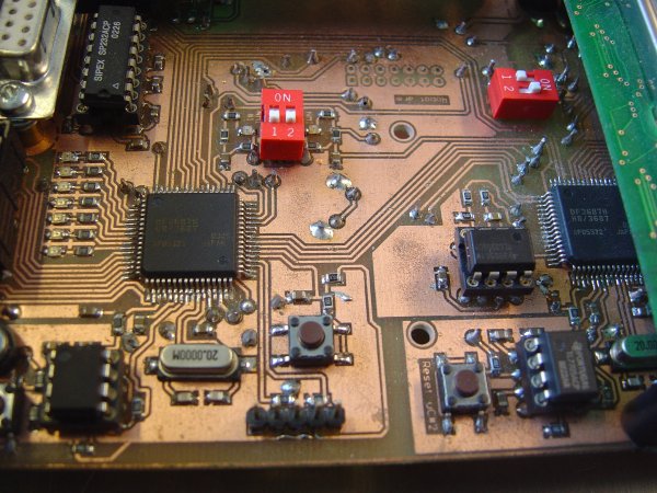
The electronics of the robot is divided into two parts; the control unit and the communication unit. In each unit is placed a microcontroller from Renesas with 16-bit architecture named H8/3687 which e.g. features
Both microcontrollers are operating at a frequency of 20 MHz.
DC/DC converter
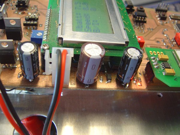
The DC/DC converter is a step-down converter build around the L5970 switching regulator which e.g. features a 250 kHz internal oscillator, up to 1 A output current and the switching MOSFET.
Bluetooth link
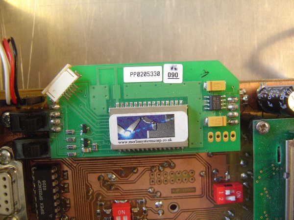
The bluetooth link is used to transfer various data generated by the sensors of the robot and the data processing. The PC software is used to display those data. The bluetooth hardware module is developed by Merlin Systems.
PC software

The PC-software is mainly used for debugging the robot. The robot transmits measured and calculated data via the Bluetooth or RS-232 link with a frequency of 10 Hz. The PC-software collects the transmitted data, stores it in a log-file and presents the data in a GUI as shown in the screenshot above.
Distance sensors
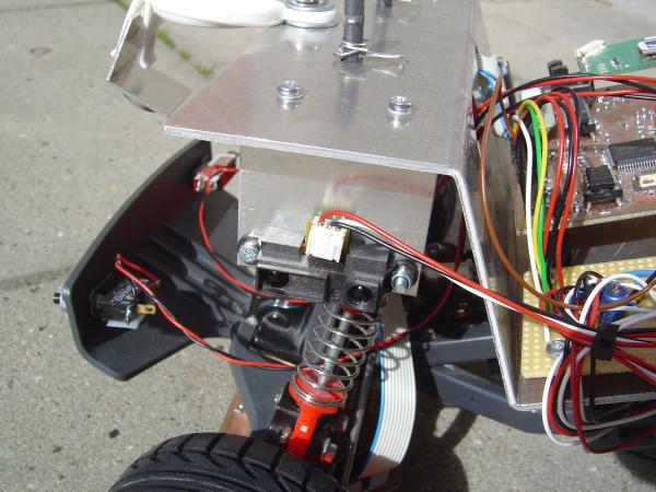
The robot has four distance sensors, two at each side. The used distance sensors are from sharp and named GP2D12. They have a detection distance of 10 cm to 80 cm.
Bumper
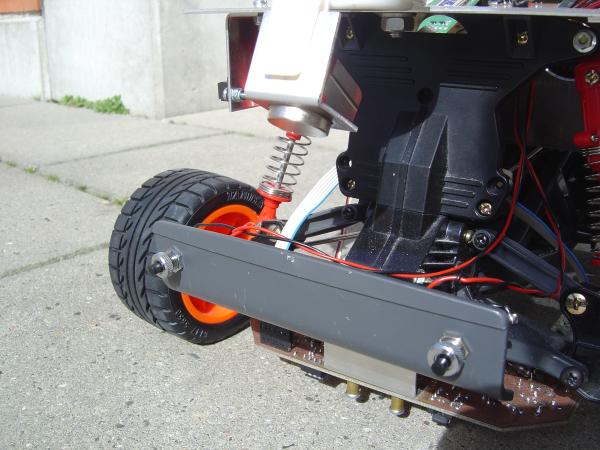
The bumper consists of two switches and is used to detect if the front of the robot hits any objects.
Magnet
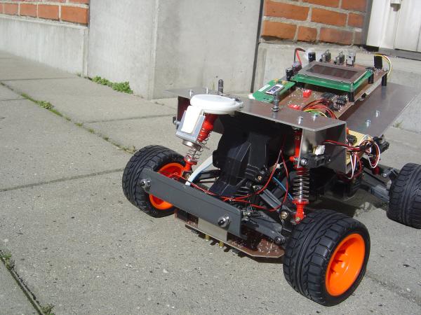
The main purpose of the magnet is to open the metallic door in the tunnel hurdle. It consists of a small, but strong permanent magnet and a retractor like those used for lift cards in ski lifts.
Downloads
Here you can download documents and videos related to the project. Note that not all videos play directly in the browser.
Videos
Development i 2006
RoboCup 2007
RoboCup 2008
RoboCup 2009
RoboCup 2010
Documents
Pictures
Here you can see and download more pictures.


